Introduction
In the first post in this series, we built a home router using NixOS. The router has vlans and firewall rules. To keep things simple, the router is directly connected to my laptop and the laptop has virtual network adapters for each vlan. We used tcpdump, Wireshark and nftrace to capture and learn about the ICMP and DHCP traffic that happens at connection time. Finally we took a look at some MTU issues.
Now that we’ve seen how the basics of the router work with just one machine connected, we’re going to build out the network with a managed switch and an access point. These are made by Ubiquiti, but we’re not going to enable any could services to manage them. Management will be done on the local network using Unifi Controller software. You can see the details on all these devices in the hardware section of the first post.
Step 1 - Install the Unifi Controller software
To manage the Unifi switches and APs, you need to have the Unifi controller on the network. It’s a web server that let’s you configure devices and get live into. I’m not going to get into this too much. There is a plethora of material about it online. I ended up using the linuxserver/unifi-controller docker image after failing to get the debian package for the controller to work. I want the controller to be as simple as possible. It runs as a stand alone Java app on MacOS and Windows, but I don’t have Java installed right now on my Mac, and I’d like to keep it that way. I just need to be able to start up the controller, log in and make some config changes, back up the config database, and turn it off.
Step 2 - Attaching network equipment
We’re going to assign a static IP address to the crappy blue HP laptop that’s running the Unifi controller. Then we’ll plug in the switch and access point. Here is the new nix configuration to tell the DHCP service. The laptop is called net-mgr, and we’re sticking it on the default non-vlan subnet.
dhcpd4 = {
      enable = true;
      interfaces = [ "enp2s0" "lan" "iot" "guest" ];
      machines = [
        { hostName = "net-mgr"; ethernetAddress = "b4:b6:86:de:05:50"; ipAddress = "192.168.0.50"; } # ethernet
      ];
      extraConfig = ''
        ...
      ''
We apply those changes using the shell script from part one and then connect the net-mgr laptop to the switch.
Step 3 - Configure Unifi switch and AP
Next we bring up the Unifi Controller software. The Controller will find Unifi devices on the network, and we will adopt them.
Configure VLANS in the Unifi Controller
In the Unifi console, we need to make a network for each vlan and our default physical network. This is done under Settings > Networks. In this example you can see the settings are pretty minimal. We give it a name, which could be anything, but we want it to match the vlan name in the router. For the purpose we specify VLAN Only in order to bypass all the DHCP settings that we would normally need to provide to a Unifi router, if we were using their USG or Dream Machine.
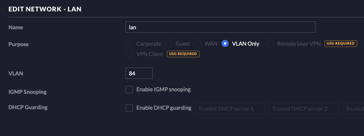
We create three vlans and one default Corporate type network to end up with the following four networks.

Configure Wi-Fi networks in the Unifi Controller
Next we create four wireless networks in the Unifi Controller. We give them each a name that makes sense, choose a security type and provide a password. Most importantly, we assign one of the VLANS (or the default network) to each Wi-Fi network. The access point will take care of adding the correct vlan tag to packets coming our of the Wi-Fi networks. Also it will route incoming VLAN tagged packets to the matching Wi-Fi network.
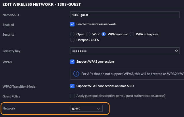
We end up with the following four Wi-Fi networks defined in the Unifi Controller.

Create switch port profiles
Each switch port can be configured independently. Switch Port Profiles are automatically created for each port. They are found under Settings > Profiles and choose the Switch Ports tab. If you need to, which you should not, you can create additional profiles. Within each port profile, there are many settings. I am only interested in the Native Network. This settings can be used to bond a port to a single VLAN or to any of the defined networks. The preexisting All profile is used for trunk ports and it has the default network configured as it’s native network.

Assign VLANS to switch ports in the Unifi Controller
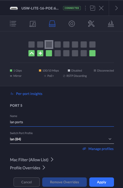
The last step in configuring the switch and access point is to assign VLANS to some of the physical ports in the switch using port profiles. I have a 16 port switch, so I’m going to assign four ports to each of the three vlans, and use the remaining four ports for the default network (the All profile). Trunk ports can carry traffic for any VLAN or no VLAN at all. We must connect the Access points to a trunk port since they need to have traffic for all vlans.
This is done under Devices in the Unifi Controller. Choose the switch, and select the Ports tab. From there, each port can be assigned one of the Port Profiles.
Resulting network
Now our physical network in the lab looks like this.
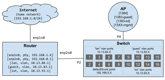
And our virtual network looks like this.
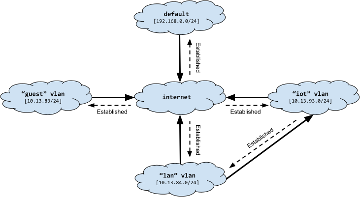
The default network is a home for devices that do not live on a VLAN. This is mainly the networking hardware itself, including the physical port on the router that connects to the switch, the switch trunk ports, and the ethernet port on the access point. I believe that Unifi gear defaults to 192.168.1.X. Currently my home network in using that subnet. But when I go live with this lab setup, I’ll switch default over to 192.168.1.X.
With this VLAN setup, guests can access the internet, but no devices in the trusted “lan” nor “iot” or “default”. Trusted devices on “lan” can access devices on “iot”. For example, an iPhone on “lan” can Airplay to smart TV on “iot” (but that will likely require some additional features for service discovery that we will add later).
Threat model
The threat model for this network includes the following.
- The software supply chain for an IoT device is compromised. The device is now running attacker-controlled software. We do not want that IoT device to be used as a jumping off point to the rest of the network devices, like our laptops, desktops, smartphones, or file/media servers.
- The IoT device is not compromised, but the vender of the device is using it to collect more data on us than we would like.
The mitigation for #1 is simply the virtual network isolation. We would like to verify it’s working. I performed a simple ping test from “guest”, and “iot” to a device on “lan”. The pings were not successful. I verified that the device I was pinging actually responds to pings, by pinging it from another device on “lan”. I also verified that I could ping from “lan” to “iot”. To get in the mindset of an attacker, we can search for something like “attack vlan compromise” and find a find a page listing vlan attacks. Many of these are pretty sophisticated, involving vulnerabilities in the implementation of the switch or router. The Double Tagging attack stood out as being easy for an attacker, and also easy to mitigate. It’s mitigated by not allowing anyone on VLAN 1, which we are not. Before I’d concern myself with mitigations for other attacks, I would use TailScale.
Going live with the new network
Check out part three, Lab to Live Home Network
 JJP Software